XDNA2 Kernel#
While all optimization objectives stated in the XDNA1 Kernel chapter remain valid, transferring BFP16 data is more complex than transferring BF16 data.
Therefore, we use a different L1 data layout to account for the pipelined BFP16 loads and stores described in the XDNA2 ISA section.
In contrast to the XDNA1 kernel, the XDNA2 kernel presented here is parametrized: the sizes m2, n2, and k1 are passed as runtime arguments rather than being fixed at assembly time.
L1 Data Layout#
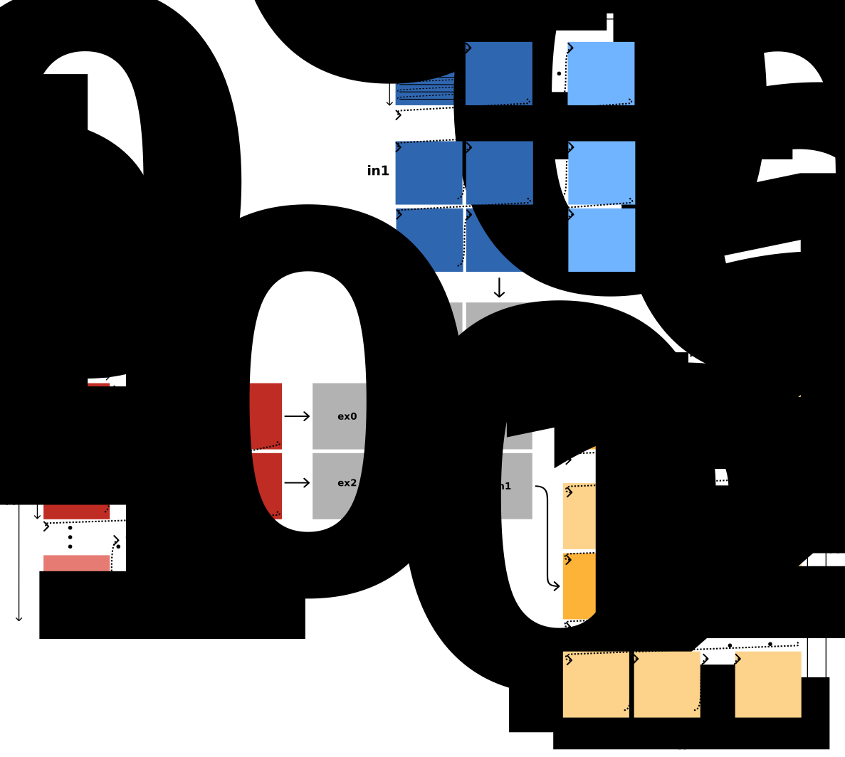
Fig. 3 Data layout of the tensor contraction kernel in the L1 scratchpad memory of an executing compute tile.
Each colored square is one 8×8 tile, the amount of data held by one register.
The order of each tensor in L1 address space is shown by the arrows.
The tensor out is spread over two memory banks.
The first computation of a 2×2 block of output tiles is in darker colors, and it consumes the whole of k1: the vector registers (EX) stream the input tiles along the k1 dimension with a fixed m1 or n1 index.
Each accumulator register (DM) is labeled with its corresponding (m1, n1) index.#
Fig. 3 illustrates the data layout of the BFP16 tensor contraction kernel with FP32 accumulation: [m2,k1,m1,m0,k0],[n2,k1,n1,n0,k0]->[m1,m2,n2,n1,m0,n0].
The tensors are tiled based on the BFP16 VMAC.F operation requirements, meaning that all three tensors use 8×8 tiles.
In detail, in0 has tiles of size |m0|×|k0|, in1 of size |n0|×|k0|, and out of size |m0|×|n0|, where |m0|=8, |k0|=8, and |n0|=8.
A BFP16 input tile, that is, a tile of either in0 or in1, has a size of 72 bytes.
An FP32 tile of out has a size of 256 bytes.
Compared to the XDNA1 kernel’s layout, the L1 data layout is further complicated by the need to avoid bank conflicts.
Specifically, XDNA2 has a total of four logical memory banks.
We assign one of the banks to in0 and another one to in1.
This leaves two banks for loading and storing the output tensor out.
To fully utilize both banks, our L1 data layout evenly distributes the output tensor across the two banks.
Accordingly, m1 is the outermost dimension of the output tensor, where the slice with m1=0 is placed on one bank and the slice with m1=1 on the other.
The kernel employs a 2×2 register blocking for the output tensor, as described in Section Register Blocking.
This blocking consumes the dimensions m1 and n1 with |m1|=2 and |n1|=2 in the einsum.
Each of the four output tiles of the register blocking, shown in gray, has the size of one accumulator register (DM).
XDNA2 has only five accumulator registers.
A naive assignment of the four output tiles to four accumulator registers would leave only one for buffering.
One register for buffering the next iteration’s four output tiles is not enough, as this would not allow all L1 data transfers to be hidden behind compute.
Therefore, we developed a technique which allows the time-multiplexing of four output tiles onto only two accumulator registers, freeing up three registers for buffering.
Section Accumulation Chains explains how the time-multiplexing is achieved, and Section Accumulator Register Buffering describes how three registers are enough for hiding the load and store of four tiles each behind compute.
The sizes of the remaining dimensions m2, n2, and k1 are runtime parameters.
In addition to the size restrictions described in Section Runtime Parametrization, their sizes must be chosen so that the tensors fit into the L1 scratchpad.
Design Decisions#
As discussed in the previous section, our L1 data layout can be expressed by the einsum [m2,k1,m1,m0,k0],[n2,k1,n1,n0,k0]->[m1,m2,n2,n1,m0,n0] with the fixed sizes |m0|=8, |k0|=8, |n0|=8, |m1|=2, and |n1|=2.
Similar to the XDNA1 kernel, the VMAC.F operation consumes the dimensions m0, k0, and n0.
Dimensions m1 and n1 represent our accumulator blocking, and |m2|, |k1|, and |n2| are runtime parameters.
Before discussing the design decisions of our XDNA2 tensor contraction kernel, we summarize key hardware properties that must be considered:
Loading data into a 256-byte accumulator register requires four 64-byte loads. VLDA can load directly into the accumulator registers. However, VLDB can only load into vector registers. Each 64-byte load has a latency of seven cycles. A VMOV operation copies 64 bytes from a vector register into an accumulator register and has a latency of two cycles.
VMAC.F reads from the accumulator register in its fourth cycle (forwarding).
Properties 1 and 2 allow us to formulate scheduling rules when a VMAC.F operation depends on loads to the accumulator register. Specifically, we can issue a VMAC.F operation at the earliest in the fifth cycle of the fourth 64-byte load. In other words, the last load and the dependent VMAC.F must be four cycles apart.
Loading a 72-byte vector register requires one VLDA.POP or VLDB.POP from a pre-filled load pipeline. This load has a latency of eight cycles.
A VMAC.F operation has a latency of six cycles.
Writes into the 512-bit views (
<BMLLd>|<BMLHd>|<BMHLd>|<BMHHd>) of each 2048-bit accumulator register (<DMd>) share the same single write port that accepts one write per cycle. For example, a VMOV issued five instructions after a VLDA performs its write-back in the same cycle as that VLDA. If both target the same accumulator register, one of the two writes is lost.
Runtime Parametrization#
Unlike the fixed-size XDNA1 kernel, this kernel receives the sizes m2, n2, and k1 at runtime.
The four buffer pointers are passed in P0 (in0), P1 (in1), P2 (out for m1=0), and P3 (out for m1=1), followed by the three sizes in the scalar registers R0 (|m2|), R1 (|n2|), and R2 (|k1|).
The parameters must satisfy |m2|·|n2| ≥ 2 and |k1| % 4 == 0 with |k1| ≥ 8.
These constraints follow from the software pipelining discussed below: the m2 and n2 iterations peel the first and last 2×2 blocks of output tiles into a warm-up and a cool-down phase (hence |m2|·|n2| ≥ 2), and the k1 contraction is executed by a loop that is unrolled by four k1 steps with an eight-step pipeline fill and drain peeled around it (hence |k1| divisible by four and at least eight).
Output Stationary#
See Output Stationary in the XDNA1 kernel design.
Register Blocking#
The kernel uses a 2×2 register blocking which is mapped onto the dimensions m1 and n1 with |m1|=|n1|=2.
A k1 step is then four VMAC.F operations over four operand registers but only two accumulator registers, as shown in Fig. 4.
The two output tiles of an m1 row can share an accumulator register because the accumulation chains below schedule the two tiles one after the other.
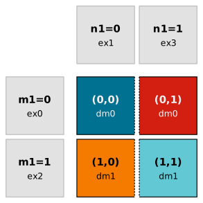
Fig. 4 One 2×2 block of output tiles labeled with their corresponding (m1, n1) index and the primary accumulator register that holds the tile.
Every output tile is computed by one VMAC.F operation with the corresponding input tiles, e.g., vmac.f dm0, dm0, ex0, ex1, r20 computes (0,0).
The dashed edge indicates that two tiles share one accumulator register in turn; the colors match the ones the accumulation-chain figures use for the four chains.#
Streaming of Input Tiles#
The L1 data layout stores the input tiles of in0 in k1×m1 blocks and the tiles of in1 in k1×n1 blocks, as displayed by the arrows in Fig. 3.
Thus, for the computation of a 2×2 block of output tiles, we can use one linear stream (through load unit A) to load the data of in0 and one (through load unit B) to load the data of in1.
The highest L1-load performance is obtained when consecutively loading eight 72-byte tiles on one load unit, costing nine operations.
Additionally, the load streams must be 64-byte aligned.
Bank-Aware Buffer Placement#
We split the output tensor into two parts along the m1 dimension, as shown by the wide gap across out in Fig. 3, allowing for simultaneous access to both halves without bank conflicts.
In detail, we place the output tensor in two buffers that lie in two different memory banks.
The implementation passes two pointers for out, one per half.
Looped Contraction Dimension#
Because k1 is now a runtime parameter, the kernel cannot fully unroll the contraction as the XDNA1 kernel does.
Instead, the k1 dimension is executed by a counted loop that is unrolled by four k1 steps: each loop iteration issues 16 VMAC.F operations, four for every k1 step of the 2×2 block.
The loop is software-pipelined, so eight k1 steps are peeled out of the loop to fill and drain the accumulator pipeline.
Consequently, the trip count is (|k1| − 8) / 4, which requires |k1| % 4 == 0 and |k1| ≥ 8.
Accumulation Chains#
XDNA2 has only five 2048-bit accumulator registers. Therefore, we cannot use a simple double-buffering scheme for the 2×2 register blocking, which would require eight registers.
The VMAC.F operation reads the input accumulator register in the fourth cycle and writes the output accumulator register in the sixth cycle. Thus, VMAC.F operations accumulating in a single output tile must be scheduled at least three cycles apart, as shown in Fig. 5.
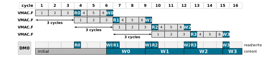
Fig. 5 Minimum spacing of the VMAC.F operations inside a single accumulation chain.
Each operation is drawn as its six pipeline stages: it reads the accumulator register in its fourth cycle and writes it in its sixth; the read is in the first half of the cycle and the write in the second.
In the two DM0 lanes, the reads R and writes W with their VMAC.F IDs show which operation uses the ports of DM0 in each cycle and which operation’s write output the register holds.#
However, the six-cycle VMAC.F operation only requires valid data in the accumulator register when it reads from the register in the fourth cycle. At all other times, the register may hold unrelated data. Assuming that we write the accumulation data for the VMAC.F in the third cycle, we can:
Write unrelated data to the accumulator register in cycles 1–2 and 4–5.
Read unrelated data from the accumulator register in cycles 1–3 and 5–6.
In practice, our kernel schedules the VMAC.F accumulation chains with a distance of four cycles, as shown in Fig. 6.
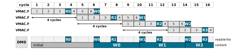
Fig. 6 Accumulation chain with the four-cycle scheduling distance. Compared to the minimum spacing, the accumulator register is left untouched in every second cycle.#
The four-cycle distance allows us to interleave two accumulation chains. The second chain has a two-cycle offset, so that it reads the accumulator register in exactly those cycles in which the first chain writes it, and vice versa. Both chains can therefore share one accumulator register, as shown in Fig. 7.
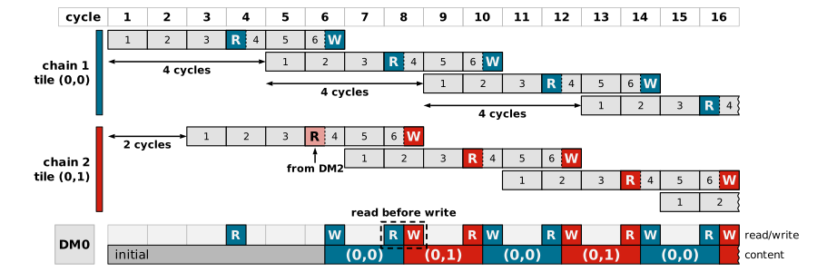
Fig. 7 Two accumulation chains sharing the accumulator register DM0.
Each chain uses a four-cycle issue distance between its operations, and the two chains are started with a two-cycle offset.
In every cycle, at most one chain uses the read port and at most one of the write ports.
DM0 is time-multiplexed between the partial sums of the output tiles (m1,n1) = (0,0) and (0,1): each chain reads its own value back two cycles after writing it, while the other chain’s write reaches the register in that same cycle.
The highlighted cycle shows why this is safe: the read falls in the first half of the cycle, the write in the second.
Only the first read of the second chain takes its input from another register, since the warm-up loads that output tile into DM2.#
We see that we obtain an execution throughput of 1/2 from cycle 6 onwards, that is, in every other cycle a VMAC.F operation completes.
We obtain an execution throughput of 1 by scheduling two additional interleaved chains on the accumulator register DM1, as shown in Fig. 8.
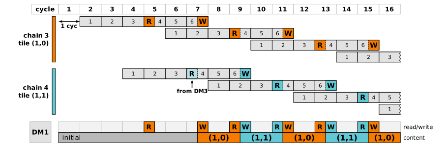
Fig. 8 Two further accumulation chains, sharing the accumulator register DM1 and started with a one-cycle offset to the chains on DM0.#
These two interleaved chains have a one-cycle offset compared to the previous ones, so a VMAC.F operation now completes in every cycle from cycle 6 onwards.
In summary, to fully utilize the vector unit, our kernel uses two accumulator registers and four accumulation chains, as shown in Fig. 9.
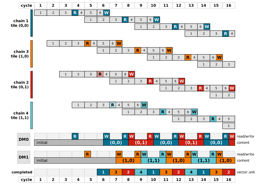
Fig. 9 The complete schedule of the four accumulation chains on the accumulator registers DM0 and DM1.
Each chain accumulates one of the four output tiles of the 2×2 register blocking, and the chains are issued one cycle apart.
DM0 is time-multiplexed between the tiles (0,0) and (0,1), and DM1 between (1,0) and (1,1).
The bottom lane marks the VMAC.F operation that completes in each cycle, colored and labeled with the number of its chain: from cycle 6 onwards, one VMAC.F operation completes in every cycle.#
We use the remaining three accumulator registers for hiding the L1-register transfers.
Fused m2/n2 Loop#
The m2 and n2 iterations are implemented using a single fused loop over the combined index.
As in the XDNA1 kernel, the first and last 2×2 blocks of output tiles are computed outside of this loop, forming a warm-up and a cool-down phase.
The loop uses a counter register initialized to |m2|·|n2| − 2 and a delayed conditional branch; the k1 loop described in Section Looped Contraction Dimension is nested inside every iteration.
Because the fused m2/n2 loop and the k1 loop are nested, the kernel uses conditional branches instead of the hardware loop of the fixed-size XDNA1 kernel.
Accumulator Register Buffering#
To summarize, given the einsum [m2,k1,m1,m0,k0],[n2,k1,n1,n0,k0]->[m1,m2,n2,n1,m0,n0] and the data layout shown in Fig. 3, m0, k0, and n0 are consumed by the BFP16 VMAC.F operations.
m1 and n1 are used for our 2×2 accumulator blocking.
Dimension k1 is consumed by the k1 loop.
Since k0 and k1 are the only contraction dimensions, after performing all k1 updates, we have fully computed a 2×2 block of output tiles.
Next, we advance the last two remaining dimensions, n2 and m2, through the fused loop, where n2 is the faster dimension.
When advancing from one 2×2 block of output tiles i to the next (i+1), we must write i to the L1 scratchpad and load i+1.
In general, the tensor contraction kernel writes the data of block i during the computation of block i+1 and reads the accumulator input for i+1 during the computation of i.
This approach allows us to hide L1-register transfers behind VMAC.F operations.
We realize this scheme with the remaining three accumulator registers DM2–DM4, which hold one buffer slot per output tile of the 2×2 block.
That is one slot more than we have registers, so DM2 buffers two output tiles.
A slot serves both directions: the VMAC.F operation that finishes an output tile of block i writes its result into the slot, from where it is saved, and the VMAC.F operation that starts the output tile with the same (m1, n1) index of block i+1 takes its accumulator input out of the slot.
Both operations use the slot in the same cycle, as shown in Fig. 10.
The saving and loading of the tiles occurs in four operations each, one operation for each 512-bit view (<BMLLd>|<BMLHd>|<BMHLd>|<BMHHd>) of a 2048-bit accumulator register (<DMd>).
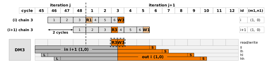
Fig. 10 Register DM3 buffers the (1,0) output tile.
The column id (m1,n1) shows to which iteration and output tile each operation belongs.
R1, R3 and W1, W3 label the reads and writes by the register they touch.
DM3 is drawn as its port lane over one row per 512-bit view.
Gray is the input for block i+1, orange the finished tile of block i; L and S mark where a quarter is loaded and saved.
The cycle where both operations meet and the register value changes is marked by a dashed box.#
A VMAC.F operation reads from the source accumulator register in its fourth cycle and writes to the destination in its sixth cycle.
By scheduling the operation that finishes block i at most two cycles before the one that starts block i+1, the read of the latter is executed before the write of the former, and a single slot suffices for both directions.
A single iteration j of the fused loop mostly contains VMAC.F operations that compute a single block i of output tiles.
However, at the beginning of the iteration, two operations finish the computation of block i-1, while at the end of the iteration two operations already start computing block i+1.
The eight operations of two consecutive iterations therefore meet at the boundary from one block to the next, in the order in which they are issued:
the fourth-to-last and third-to-last VMAC.F operations of iteration
jfinish blockiand write toDM2andDM3;the last two VMAC.F operations of iteration
jstart blocki+1and read fromDM2andDM3;the first two VMAC.F operations of iteration
j+1finish blockiand write toDM4andDM2;the following two VMAC.F operations of iteration
j+1start blocki+1and read fromDM4andDM2.
Fig. 11 shows the four pairs and the three buffer registers together.
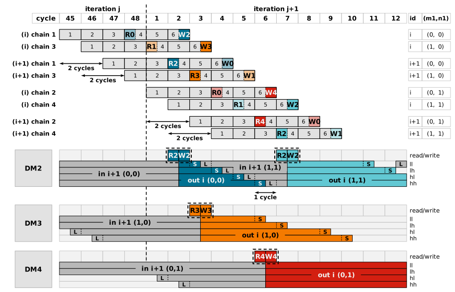
Fig. 11 The eight VMAC.F operations of (a)–(d), each labeled with the block it belongs to and its accumulation chain, and the three registers through which the four output tiles are transferred.
The VMAC.F operations of cycles 5–12 only accumulate, in DM0 and DM1, and are left out.
DM2 is reused for two tiles: (0,0) is stored to one memory bank and (1,1) to the other.
The 1 cycle annotation marks a one-cycle spacing: the last quarter of that second input lands one cycle before it is read, which is the tightest spacing the four-cycle load-to-VMAC.F minimum allows.#
Output Tile Prioritization#
As discussed in the section Fused m2/n2 Loop, the tensor contraction kernel ends with a specialized cool-down phase. During this phase, the kernel computes the last 2×2 block of output tiles. Unlike in a “regular” iteration of the fused loop, we cannot hide the final store operations behind following loop iterations. Thus, we prioritize the computation of one output tile, so that the register-L1 transfers are at least partially hidden behind VMAC.F operations of the cool-down phase.
Implementation#
This section discusses the warm-up phase, fused loop, and cool-down phase of the parametrized XDNA2 BFP16 tensor contraction kernel.
As described in sections L1 Data Layout and Design Decisions, the einsum [m2,k1,m1,m0,k0],[n2,k1,n1,n0,k0]->[m1,m2,n2,n1,m0,n0] with fixed sizes |m0|=|k0|=|n0|=8, |m1|=2, and |n1|=2 describes the tensor contraction kernel.
Listing 10 shows the header of the kernel, which documents its einsum, runtime parameters, and register allocation.
 7// m1, m2 n2 n1 m0 n0 += m2 k1 m1 m0 k0, n2 k1 n1 n0 k0
 8//   += : read==write f32 accumulator; m1, => |m1| buffers (p2,p3)
 9//
10// Parameters
11// p0  = in0
12// p1  = in1
13// p2  = out[m1==0]
14// p3  = out[m1==1]
15// r0  = |m2|
16// r1  = |n2| (|m2| * |n2| >= 2)
17// r2  = |k1| (|k1|%4 == 0 and |k1| >= 8)
18// |m1| = |n1| = 2
19// |m0| = |n0| = |k0| = 8
20
21// Variables
22// r3  = m2n2_i % r1
23// r4  = jumpback in IN0 (|k1| * r19)
24// r5  = jumpback in IN1 (|n2| * r4)
25
26// r6 = r4 or 0 (current jump in IN0)
27// r7 = r5 or 0 (current jump in IN1)
28
29// r16 = k1_i
30// r17 = m2n2_i
31
32// r19 = -1 * 72(bfp16_block_byte_size) * 2(|m1| or |n1|)
33// r20 = 780 (vmac.f config)
34// r21 = 1 (for xor)
35
36// m0  = r6
37// m1  = r7
38
39// Functional Units:
40// Vector Unit (V)                 ; Load Unit A (A)                   ; Load Unit B (B)                   ; Store Unit (S)       ; Scalar Unit (X)   ; Move Unit (M)
41//                                                                                                                                ; or Scalar + Move Unit (XM)
For the benchmark, we invoke the kernel with the runtime arguments |m2|=4, |n2|=4, and |k1|=12, which yields a tensor contraction with the same number of multiply-accumulate operations (MACs) as a matrix multiplication with M=64, K=96, and N=64.
The performance results presented in Section Kernel Efficiency use this configuration.
Warm-up Phase#
 43  nopv                             ; vlda bmll0, [p2, #0  ]            ; vldb x8,  [p3, #0  ]              ; movs p4, p2          ; movx r24, #0      ; mov r25, #0
 44  nopv                             ; vlda bmlh0, [p2, #64 ]            ; vldb x9,  [p3, #64 ]              ; movs p5, p3          ; nopx              ; mov r23, p7
 45  nopv                             ; vlda bmhl0, [p2, #128]            ; vldb x10, [p3, #128]              ; padds [p4], #256     ; movxm p7, #.l_mn_loop_start
 46  nopv                             ; vlda bmhh0, [p2, #192]            ; vldb x11, [p3, #192]              ; padds [p5], #256     ; movxm r19, #-72 * 2
 47
 48// 4
 49  nopv                             ; vlda.fill.512 [p0, lf0, r24]      ; vldb.fill.512 [p1, lf1, r25]      ; nops                 ; mul r17, r0,  r1  ; nopm
 50  nopv                             ; vlda.pop.576 ex0,  [p0, lf0, r24] ; vldb.pop.576 ex1,  [p1, lf1, r25] ; nops                 ; mul r4,  r19, r2  ; nopm
 51  nopv                             ; vlda.pop.576 ex2,  [p0, lf0, r24] ; vldb.pop.576 ex3,  [p1, lf1, r25] ; nops                 ; add r17, r17, #-2 ; nopm
 52  nopv                             ; nopa                              ; nopb                              ; nops                 ; movx r21, #1      ; nopm
 53
 54// 8
 55  nopv                             ; vlda bmll2, [p4], #64             ; vldb x8,  [p5], #64               ; nops                 ; nopx              ; nopm
 56  nopv                             ; vlda bmlh2, [p4], #64             ; vldb x9,  [p5], #64               ; nops                 ; nopx              ; vmov bmll1, x8
 57  nopv                             ; vlda bmhl2, [p4], #64             ; vldb x10, [p5], #64               ; nops                 ; nopx              ; vmov bmlh1, x9
 58  nopv                             ; vlda bmhh2, [p4], #64             ; vldb x11, [p5], #64               ; nops                 ; nopx              ; vmov bmhl1, x10
 59  nopv                             ; vlda.pop.576 ex4,  [p0, lf0, r24] ; vldb.pop.576 ex5,  [p1, lf1, r25] ; nops                 ; nopx              ; vmov bmhh1, x11
 60  nopv                             ; vlda.pop.576 ex6,  [p0, lf0, r24] ; vldb.pop.576 ex7,  [p1, lf1, r25] ; nops                 ; movx r3, #0       ; nopm
 61  nopv                             ; vlda.pop.576 ex8,  [p0, lf0, r24] ; vldb.pop.576 ex9,  [p1, lf1, r25] ; nops                 ; mul r5,  r4,  r1  ; nopm
 62  nopv                             ; vlda.pop.576 ex10, [p0, lf0, r24] ; vldb.pop.576 ex11, [p1, lf1, r25] ; nops                 ; movx r20, #780    ; nopm
 63
 64// 16
 65  vmac.f dm0, dm0, ex0,  ex1,  r20 ; vlda.pop.576 ex0,  [p0, lf0, r24] ; vldb.pop.576 ex1,  [p1, lf1, r25] ; nops                 ; add r3,  r3,  #1  ; nopm
 66  vmac.f dm1, dm1, ex2,  ex1,  r20 ; vlda.pop.576 ex2,  [p0, lf0, r24] ; vldb.pop.576 ex3,  [p1, lf1, r25] ; nops                 ; ltu r6,  r3,  r1  ; vmov bmll3, x8
 67  vmac.f dm0, dm2, ex0,  ex3,  r20 ; vlda bmll2, [p4], #64             ; nopb                              ; nops                 ; mul r3,  r3,  r6  ; vmov bmlh3, x9
 68  vmac.f dm1, dm3, ex2,  ex3,  r20 ; vlda bmlh2, [p4], #64             ; vldb x4, [p5], #64                ; nops                 ; xor r7,  r6,  r21 ; vmov bmhl3, x10
 69
 70  vmac.f dm0, dm0, ex4,  ex5,  r20 ; vlda bmhl2, [p4], #64             ; vldb x5, [p5], #64                ; nops                 ; mul r6,  r6,  r4  ; vmov bmhh3, x11
 71  vmac.f dm1, dm1, ex6,  ex5,  r20 ; vlda bmhh2, [p4], #64             ; vldb x6, [p5], #64                ; nops                 ; mul r7,  r7,  r5  ; nopm
 72  vmac.f dm0, dm0, ex4,  ex7,  r20 ; nopa                              ; vldb x7, [p5], #64                ; nops                 ; nopx              ; mov m0, r6
 73  vmac.f dm1, dm1, ex6,  ex7,  r20 ; vlda.fill.512 [p0, lf0, r24]      ; vldb.fill.512 [p1, lf1, r25]      ; nops                 ; nopx              ; mov m1, r7
 74
 75  vmac.f dm0, dm0, ex8,  ex9,  r20 ; vlda.pop.576 ex0,  [p0, lf0, r24] ; vldb.pop.576 ex1,  [p1, lf1, r25] ; nops                 ; nopxm
 76  vmac.f dm1, dm1, ex10, ex9,  r20 ; vlda.pop.576 ex2,  [p0, lf0, r24] ; vldb.pop.576 ex3,  [p1, lf1, r25] ; nops                 ; add r16, r2,  #-8 ; nopm
 77  vmac.f dm0, dm0, ex8,  ex11, r20 ; vlda.pop.576 ex4,  [p0, lf0, r24] ; vldb.pop.576 ex5,  [p1, lf1, r25] ; nops                 ; jz r16, #.l_k1_end_warm_up
 78  vmac.f dm1, dm1, ex10, ex11, r20 ; vlda.pop.576 ex6,  [p0, lf0, r24] ; vldb.pop.576 ex7,  [p1, lf1, r25] ; nops                 ; nopxm                                 // Delay Slot 5
 79
 80  vmac.f dm0, dm0, ex0,  ex1,  r20 ; vlda.pop.576 ex8,  [p0, lf0, r24] ; vldb.pop.576 ex9,  [p1, lf1, r25] ; nops                 ; nopx              ; vmov bmll3, x4    // Delay Slot 4
 81  vmac.f dm1, dm1, ex2,  ex1,  r20 ; vlda.pop.576 ex10, [p0, lf0, r24] ; vldb.pop.576 ex11, [p1, lf1, r25] ; nops                 ; nopx              ; vmov bmlh3, x5    // Delay Slot 3
 82  vmac.f dm0, dm0, ex0,  ex3,  r20 ; vlda.pop.576 ex0,  [p0, lf0, r24] ; vldb.pop.576 ex1,  [p1, lf1, r25] ; nops                 ; nopx              ; vmov bmhl3, x6    // Delay Slot 2
 83  vmac.f dm1, dm1, ex2,  ex3,  r20 ; vlda.pop.576 ex2,  [p0, lf0, r24] ; vldb.pop.576 ex3,  [p1, lf1, r25] ; nops                 ; nopx              ; vmov bmhh3, x7    // Delay Slot 1
 84
 85.p2align 4
 86.l_k1_start_warm_up:
 87  vmac.f dm0, dm0, ex0,  ex1,  r20 ; nopa                              ; nopb                              ; nops                 ; nopxm
 88  vmac.f dm1, dm1, ex2,  ex1,  r20 ; nopa                              ; nopb                              ; nops                 ; nopxm
 89  vmac.f dm0, dm0, ex0,  ex3,  r20 ; nopa                              ; nopb                              ; nops                 ; nopxm
 90  vmac.f dm1, dm1, ex2,  ex3,  r20 ; nopa                              ; nopb                              ; nops                 ; nopxm
 91
 92  vmac.f dm0, dm0, ex4,  ex5,  r20 ; nopa                              ; nopb                              ; nops                 ; nopxm
 93  vmac.f dm1, dm1, ex6,  ex5,  r20 ; nopa                              ; nopb                              ; nops                 ; nopxm
 94  vmac.f dm0, dm0, ex4,  ex7,  r20 ; nopa                              ; nopb                              ; nops                 ; nopxm
 95  vmac.f dm1, dm1, ex6,  ex7,  r20 ; vlda.fill.512 [p0, lf0, r24]      ; vldb.fill.512 [p1, lf1, r25]      ; nops                 ; nopxm
 96
 97  vmac.f dm0, dm0, ex8,  ex9,  r20 ; vlda.pop.576 ex0,  [p0, lf0, r24] ; vldb.pop.576 ex1,  [p1, lf1, r25] ; nops                 ; nopxm
 98  vmac.f dm1, dm1, ex10, ex9,  r20 ; vlda.pop.576 ex2,  [p0, lf0, r24] ; vldb.pop.576 ex3,  [p1, lf1, r25] ; nops                 ; add r16, r16, #-4 ; nopm
 99  vmac.f dm0, dm0, ex8,  ex11, r20 ; vlda.pop.576 ex4,  [p0, lf0, r24] ; vldb.pop.576 ex5,  [p1, lf1, r25] ; nops                 ; jnz r16, #.l_k1_start_warm_up
100  vmac.f dm1, dm1, ex10, ex11, r20 ; vlda.pop.576 ex6,  [p0, lf0, r24] ; vldb.pop.576 ex7,  [p1, lf1, r25] ; nops                 ; nopxm                                 // Delay Slot 5
101
102  vmac.f dm0, dm0, ex0,  ex1,  r20 ; vlda.pop.576 ex8,  [p0, lf0, r24] ; vldb.pop.576 ex9,  [p1, lf1, r25] ; nops                 ; nopxm                                 // Delay Slot 4
103  vmac.f dm1, dm1, ex2,  ex1,  r20 ; vlda.pop.576 ex10, [p0, lf0, r24] ; vldb.pop.576 ex11, [p1, lf1, r25] ; nops                 ; nopxm                                 // Delay Slot 3
104  vmac.f dm0, dm0, ex0,  ex3,  r20 ; vlda.pop.576 ex0,  [p0, lf0, r24] ; vldb.pop.576 ex1,  [p1, lf1, r25] ; nops                 ; nopxm                                 // Delay Slot 2
105  vmac.f dm1, dm1, ex2,  ex3,  r20 ; vlda.pop.576 ex2,  [p0, lf0, r24] ; vldb.pop.576 ex3,  [p1, lf1, r25] ; nops                 ; nopxm                                 // Delay Slot 1
106
107.p2align 4
108.l_k1_end_warm_up:
109  vmac.f dm0, dm0, ex0,  ex1,  r20 ; nopa                              ; paddb [p1], m1                    ; nops                 ; nopxm
110  vmac.f dm1, dm1, ex2,  ex1,  r20 ; nopa                              ; vldb.fill.512 [p1, lf1, r25]      ; nops                 ; nopxm
111  vmac.f dm0, dm0, ex0,  ex3,  r20 ; vlda bmll4, [p4], #64             ; nopb                              ; nops                 ; nopxm
112  vmac.f dm1, dm1, ex2,  ex3,  r20 ; vlda bmlh4, [p4], #64             ; nopb                              ; nops                 ; nopxm
113
114  vmac.f dm0, dm0, ex4,  ex5,  r20 ; padda [p0], m0                    ; nopb                              ; nops                 ; nopxm
115  vmac.f dm1, dm1, ex6,  ex5,  r20 ; vlda.fill.512 [p0, lf0, r24]      ; nopb                              ; nops                 ; nopxm
116  vmac.f dm0, dm0, ex4,  ex7,  r20 ; vlda.pop.576 ex4,  [p0, lf0, r24] ; vldb.pop.576 ex5,  [p1, lf1, r25] ; nops                 ; nopxm
117  vmac.f dm1, dm1, ex6,  ex7,  r20 ; vlda.pop.576 ex6,  [p0, lf0, r24] ; vldb.pop.576 ex7,  [p1, lf1, r25] ; nops                 ; nopxm
118
119  vmac.f dm0, dm0, ex8,  ex9,  r20 ; vlda.pop.576 ex8,  [p0, lf0, r24] ; vldb.pop.576 ex9,  [p1, lf1, r25] ; nops                 ; nopxm
120  vmac.f dm1, dm1, ex10, ex9,  r20 ; vlda.pop.576 ex10, [p0, lf0, r24] ; vldb.pop.576 ex11, [p1, lf1, r25] ; nops                 ; nopxm
121  vmac.f dm0, dm0, ex8,  ex11, r20 ; vlda bmhl4, [p4], #64             ; nopb                              ; nops                 ; jz r17, #.l_mn_loop_end
122  vmac.f dm1, dm1, ex10, ex11, r20 ; vlda bmhh4, [p4], #64             ; nopb                              ; nops                 ; add r17, r17, #-1 ; nopm              // Delay Slot 5
123
124// k=k1-1_0
125  vmac.f dm2, dm0, ex0,  ex1,  r20 ; vlda bmll2, [p5], #64             ; nopb                              ; nops                 ; nopxm                                 // Delay Slot 4
126  vmac.f dm3, dm1, ex2,  ex1,  r20 ; vlda bmlh2, [p5], #64             ; nopb                              ; nops                 ; nopxm                                 // Delay Slot 3
127// k=k1_0
128
129// k=0_0
130  vmac.f dm0, dm2, ex4,  ex5,  r20 ; vlda bmhl2, [p5], #64             ; nopb                              ; nops                 ; nopxm                                 // Delay Slot 2
131  vmac.f dm1, dm3, ex6,  ex5,  r20 ; vlda bmhh2, [p5], #64             ; nopb                              ; nops                 ; nopxm                                 // Delay Slot 1
Listing 11 shows the kernel’s warm-up phase, which computes the first 2×2 block of output tiles.
The first instructions issue the load operations for the first 2×2 block.
Load unit A can write directly into the accumulator registers.
Load unit B can only write into vector registers.
Thus, we first load to vector registers using load unit B and then copy the data to accumulator registers.
We use accumulator registers DM0–DM3 for these “loads”.
The VMAC.F operations in lines 65–122 exclusively use DM0 and DM1 as their destination registers.
Thus, registers DM2–DM4 can be used to load three of the four output tiles of the next 2×2 block, which the upcoming fused loop requires.
The warm-up phase is itself software-pipelined over k1.
Lines 43–83 fill the accumulator pipeline and issue the first k1 steps, lines 87–105 form the k1 loop, which runs (|k1| − 8) / 4 times (once for |k1|=12), and lines 109–131 compute all but the last two VMAC.F operations of the first block and prepare the second one.
The two remaining VMAC.F operations of the first block are the ones discussed as (c) in Section Accumulator Register Buffering of the kernel design; they are issued at the beginning of the first fused-loop iteration.
The scalar unit initializes the loop counters and pointer-arithmetic registers in the same instructions as the vector operations described above, for example R17 = |m2|·|n2| − 2 in line 51 and R16 = |k1| − 8 in line 76.
Line 121 skips the fused loop when |m2|·|n2| = 2; its delay slot in line 122 decrements R17 once more.
The instructions in lines 43–62 each contain a NOPV operation; hence, the vector unit is not used while the first block and input operands are loaded.
All other instructions perform VMAC.F operations.
In summary, the warm-up phase issues 4·|k1| + 16 instructions, 4·|k1| of which contain VMAC.F operations; for the benchmark configuration |k1|=12, this is 48 of 64 instructions.
Fused Loop#
Unlike the fixed-size XDNA1 kernel, this kernel does not configure a zero-overhead hardware loop with movxm ls/le/lc.
Instead, the fused m2/n2 loop closes with the delayed conditional branch jnzd r17, r17, p7 in line 197, which jumps to the address in P7 (loaded in line 45), tests R17 and then decrements it, so the body runs one more time than R17‘s entry value.
Taking the target from a register leaves the move slot of line 197 free for another operation.
The nested k1 loop closes analogously with jnz r16, #.l_k1_start_loop in line 175.
136.l_mn_loop_start:
137  vmac.f dm4, dm0, ex0,  ex3,  r20 ; vlda.pop.576 ex0,  [p0, lf0, r24] ; vldb.pop.576 ex1,  [p1, lf1, r25] ; nops                 ; add r3,  r3,  #1  ; nopm
138  vmac.f dm2, dm1, ex2,  ex3,  r20 ; vlda.pop.576 ex2,  [p0, lf0, r24] ; vldb.pop.576 ex3,  [p1, lf1, r25] ; nops                 ; ltu r6,  r3,  r1  ; nopm
139// k=k1_1
140
141// k=0_1
142  vmac.f dm0, dm4, ex4,  ex7,  r20 ; vlda.pop.576 ex4,  [p0, lf0, r24] ; vldb.pop.576 ex5,  [p1, lf1, r25] ; vst bmll2, [p2], #64 ; mul r3,  r3,  r6  ; nopm
143  vmac.f dm1, dm2, ex6,  ex7,  r20 ; vlda.pop.576 ex6,  [p0, lf0, r24] ; vldb.pop.576 ex7,  [p1, lf1, r25] ; vst bmlh2, [p2], #64 ; xor r7,  r6,  r21 ; nopm
144// k=1_1
145
146  vmac.f dm0, dm0, ex8,  ex9,  r20 ; nopa                              ; nopb                              ; vst bmhl2, [p2], #64 ; mul r6,  r6,  r4  ; nopm
147  vmac.f dm1, dm1, ex10, ex9,  r20 ; vlda bmll2, [p4], #64             ; nopb                              ; vst bmll3, [p3], #64 ; mul r7,  r7,  r5  ; vmov x9, bmhh2
148  vmac.f dm0, dm0, ex8,  ex11, r20 ; vlda bmlh2, [p4], #64             ; nopb                              ; vst bmlh3, [p3], #64 ; nopx              ; mov m0, r6
149  vmac.f dm1, dm1, ex10, ex11, r20 ; vlda.fill.512 [p0, lf0, r24]      ; vldb.fill.512 [p1, lf1, r25]      ; vst x9,    [p2], #64 ; nopx              ; mov m1, r7
150
151  vmac.f dm0, dm0, ex0,  ex1,  r20 ; vlda.pop.576 ex0,  [p0, lf0, r24] ; vldb.pop.576 ex1,  [p1, lf1, r25] ; vst bmhl3, [p3], #64 ; nopxm
152  vmac.f dm1, dm1, ex2,  ex1,  r20 ; vlda.pop.576 ex2,  [p0, lf0, r24] ; vldb.pop.576 ex3,  [p1, lf1, r25] ; vst bmhh3, [p3], #64 ; add r16, r2, #-8  ; nopm
153  vmac.f dm0, dm0, ex0,  ex3,  r20 ; vlda.pop.576 ex4,  [p0, lf0, r24] ; vldb.pop.576 ex5,  [p1, lf1, r25] ; vst bmll2, [p3], #64 ; jz r16, #.l_k1_end_loop
154  vmac.f dm1, dm1, ex2,  ex3,  r20 ; vlda.pop.576 ex6,  [p0, lf0, r24] ; vldb.pop.576 ex7,  [p1, lf1, r25] ; vst bmlh2, [p3], #64 ; nopxm                                 // Delay Slot 5
155
156  vmac.f dm0, dm0, ex4,  ex5,  r20 ; vlda.pop.576 ex8,  [p0, lf0, r24] ; vldb.pop.576 ex9,  [p1, lf1, r25] ; vst bmhl2, [p3], #64 ; nopxm                                 // Delay Slot 4
157  vmac.f dm1, dm1, ex6,  ex5,  r20 ; vlda.pop.576 ex10, [p0, lf0, r24] ; vldb.pop.576 ex11, [p1, lf1, r25] ; vst bmhh2, [p3], #64 ; nopxm                                 // Delay Slot 3
158  vmac.f dm0, dm0, ex4,  ex7,  r20 ; vlda.pop.576 ex0,  [p0, lf0, r24] ; vldb.pop.576 ex1,  [p1, lf1, r25] ; nops                 ; nopxm                                 // Delay Slot 2
159  vmac.f dm1, dm1, ex6,  ex7,  r20 ; vlda.pop.576 ex2,  [p0, lf0, r24] ; vldb.pop.576 ex3,  [p1, lf1, r25] ; nops                 ; nopxm                                 // Delay Slot 1
160
161.p2align 4
162.l_k1_start_loop:
163  vmac.f dm0, dm0, ex0,  ex1,  r20 ; nopa                              ; nopb                              ; nops                 ; nopxm
164  vmac.f dm1, dm1, ex2,  ex1,  r20 ; nopa                              ; nopb                              ; nops                 ; nopxm
165  vmac.f dm0, dm0, ex0,  ex3,  r20 ; nopa                              ; nopb                              ; nops                 ; nopxm
166  vmac.f dm1, dm1, ex2,  ex3,  r20 ; nopa                              ; nopb                              ; nops                 ; nopxm
167
168  vmac.f dm0, dm0, ex4,  ex5,  r20 ; nopa                              ; nopb                              ; nops                 ; nopxm
169  vmac.f dm1, dm1, ex6,  ex5,  r20 ; nopa                              ; nopb                              ; nops                 ; nopxm
170  vmac.f dm0, dm0, ex4,  ex7,  r20 ; nopa                              ; nopb                              ; nops                 ; nopxm
171  vmac.f dm1, dm1, ex6,  ex7,  r20 ; vlda.fill.512 [p0, lf0, r24]      ; vldb.fill.512 [p1, lf1, r25]      ; nops                 ; nopxm
172
173  vmac.f dm0, dm0, ex8,  ex9,  r20 ; vlda.pop.576 ex0,  [p0, lf0, r24] ; vldb.pop.576 ex1,  [p1, lf1, r25] ; nops                 ; nopxm
174  vmac.f dm1, dm1, ex10, ex9,  r20 ; vlda.pop.576 ex2,  [p0, lf0, r24] ; vldb.pop.576 ex3,  [p1, lf1, r25] ; nops                 ; add r16, r16, #-4 ; nopm
175  vmac.f dm0, dm0, ex8,  ex11, r20 ; vlda.pop.576 ex4,  [p0, lf0, r24] ; vldb.pop.576 ex5,  [p1, lf1, r25] ; nops                 ; jnz r16, #.l_k1_start_loop
176  vmac.f dm1, dm1, ex10, ex11, r20 ; vlda.pop.576 ex6,  [p0, lf0, r24] ; vldb.pop.576 ex7,  [p1, lf1, r25] ; nops                 ; nopxm                                 // Delay Slot 5
177
178  vmac.f dm0, dm0, ex0,  ex1,  r20 ; vlda.pop.576 ex8,  [p0, lf0, r24] ; vldb.pop.576 ex9,  [p1, lf1, r25] ; nops                 ; nopxm                                 // Delay Slot 4
179  vmac.f dm1, dm1, ex2,  ex1,  r20 ; vlda.pop.576 ex10, [p0, lf0, r24] ; vldb.pop.576 ex11, [p1, lf1, r25] ; nops                 ; nopxm                                 // Delay Slot 3
180  vmac.f dm0, dm0, ex0,  ex3,  r20 ; vlda.pop.576 ex0,  [p0, lf0, r24] ; vldb.pop.576 ex1,  [p1, lf1, r25] ; nops                 ; nopxm                                 // Delay Slot 2
181  vmac.f dm1, dm1, ex2,  ex3,  r20 ; vlda.pop.576 ex2,  [p0, lf0, r24] ; vldb.pop.576 ex3,  [p1, lf1, r25] ; nops                 ; nopxm                                 // Delay Slot 1
182
183.p2align 4
184.l_k1_end_loop:
185  vmac.f dm0, dm0, ex0,  ex1,  r20 ; vlda bmhl2, [p4], #64             ; paddb [p1], m1                    ; nops                 ; nopxm
186  vmac.f dm1, dm1, ex2,  ex1,  r20 ; vlda bmhh2, [p4], #64             ; vldb x5, [p5], #64                ; nops                 ; nopxm
187  vmac.f dm0, dm0, ex0,  ex3,  r20 ; vlda bmll4, [p4], #64             ; vldb x4, [p5], #64                ; nops                 ; nopxm
188  vmac.f dm1, dm1, ex2,  ex3,  r20 ; vlda bmlh4, [p4], #64             ; vldb x7, [p5], #64                ; nops                 ; nopxm
189
190  vmac.f dm0, dm0, ex4,  ex5,  r20 ; padda [p0], m0                    ; vldb x6, [p5], #64                ; vst bmll4, [p2], #64 ; nopxm
191  vmac.f dm1, dm1, ex6,  ex5,  r20 ; vlda.fill.512 [p0, lf0, r24]      ; vldb.fill.512 [p1, lf1, r25]      ; vst bmlh4, [p2], #64 ; nopxm
192  vmac.f dm0, dm0, ex4,  ex7,  r20 ; vlda.pop.576 ex4,  [p0, lf0, r24] ; vldb.pop.576 ex5,  [p1, lf1, r25] ; vst bmhl4, [p2], #64 ; nopxm
193  vmac.f dm1, dm1, ex6,  ex7,  r20 ; vlda.pop.576 ex6,  [p0, lf0, r24] ; vldb.pop.576 ex7,  [p1, lf1, r25] ; vst bmhh4, [p2], #64 ; nopxm
194
195  vmac.f dm0, dm0, ex8,  ex9,  r20 ; vlda.pop.576 ex8,  [p0, lf0, r24] ; vldb.pop.576 ex9,  [p1, lf1, r25] ; nops                 ; nopxm
196  vmac.f dm1, dm1, ex10, ex9,  r20 ; vlda.pop.576 ex10, [p0, lf0, r24] ; vldb.pop.576 ex11, [p1, lf1, r25] ; nops                 ; nopx              ; vmov bmll3, x5
197  vmac.f dm0, dm0, ex8,  ex11, r20 ; vlda bmhl4, [p4], #64             ; nopb                              ; nops                 ; jnzd r17, r17, p7 ; vmov bmlh3, x4
198  vmac.f dm1, dm1, ex10, ex11, r20 ; vlda bmhh4, [p4], #64             ; nopb                              ; nops                 ; nopx              ; vmov bmhl3, x7    // Delay Slot 5
199
200// k=k1-1_0
201  vmac.f dm2, dm0, ex0,  ex1,  r20 ; vlda bmll2, [p5], #64             ; nopb                              ; nops                 ; nopx              ; vmov bmhh3, x6    // Delay Slot 4
202  vmac.f dm3, dm1, ex2,  ex1,  r20 ; vlda bmlh2, [p5], #64             ; nopb                              ; nops                 ; nopxm                                 // Delay Slot 3
203// k=k1_0
204
205// k=0_0
206  vmac.f dm0, dm2, ex4,  ex5,  r20 ; vlda bmhl2, [p5], #64             ; nopb                              ; nops                 ; nopxm                                 // Delay Slot 2
207  vmac.f dm1, dm3, ex6,  ex5,  r20 ; vlda bmhh2, [p5], #64             ; nopb                              ; nops                 ; nopxm                                 // Delay Slot 1
Listing 12 shows the body of the fused loop in the XDNA2 tensor contraction kernel.
The two VMAC.F operations discussed as (a) in Section Accumulator Register Buffering of the kernel design are given by lines 201 and 202.
(b) is given by lines 206 and 207, (c) by lines 137 and 138, and (d) by lines 142 and 143.
The nested k1 loop occupies lines 163–181 and runs (|k1| − 8) / 4 times per fused-loop iteration.
VLDA operations load three of the four output tiles of the next 2×2 block directly into the accumulator registers DM2 and DM4.
The first DM2 tile (lines 147, 148, 185, and 186) and the DM4 tile (lines 187, 188, 197, and 198) are read from the P4 stream; because DM2 buffers two output tiles, its second tile is read from the P5 stream in the branch delay slots (lines 201, 202, 206, and 207).
The remaining fourth output tile is loaded into DM3 through load unit B: the VLDB operations in lines 186–188 and 190 read into the vector registers X5, X4, X7, and X6, which are copied into DM3 by the VMOV operations in lines 196–198 and 201.
This frees load unit A for the other loads and for the in0 operand pops.
The four quarters use separate vector registers, so that each VMOV can be placed where its write-back avoids that of a VLDA (hardware property 6).
Simultaneously, the four output tiles of the previous block are written back with the VST operations distributed across the loop body.
In summary, each of the 4·|k1| instructions in the loop body (48 for |k1|=12) contains a VMAC.F operation.
Thus, the vector unit is fully utilized.
Cool-down Phase#
211.l_mn_loop_end:
212// k=k1-1_1
213  vmac.f dm4, dm0, ex0,  ex3,  r20 ; vlda.pop.576 ex0,  [p0, lf0, r24] ; vldb.pop.576 ex1,  [p1, lf1, r25] ; nops                 ; nopxm
214  vmac.f dm2, dm1, ex2,  ex3,  r20 ; vlda.pop.576 ex2,  [p0, lf0, r24] ; vldb.pop.576 ex3,  [p1, lf1, r25] ; nops                 ; nopxm
215// k=k1_1
216
217// k=0_1
218  vmac.f dm0, dm4, ex4,  ex7,  r20 ; vlda.pop.576 ex4,  [p0, lf0, r24] ; vldb.pop.576 ex5,  [p1, lf1, r25] ; vst bmll2, [p2], #64 ; add r16, r2,  #-8 ; nopm
219  vmac.f dm1, dm2, ex6,  ex7,  r20 ; vlda.pop.576 ex6,  [p0, lf0, r24] ; vldb.pop.576 ex7,  [p1, lf1, r25] ; vst bmlh2, [p2], #64 ; jz r16, #.l_k1_end_cool_down
220// k=1_1
221
222  vmac.f dm0, dm0, ex8,  ex9,  r20 ; vlda.fill.512 [p0, lf0, r24]      ; vldb.fill.512 [p1, lf1, r25]      ; vst bmhl2, [p2], #64 ; nopx              ; nopm              // Delay Slot 5
223  vmac.f dm1, dm1, ex10, ex9,  r20 ; vlda.pop.576 ex8,  [p0, lf0, r24] ; vldb.pop.576 ex9,  [p1, lf1, r25] ; vst bmhh2, [p2], #64 ; nopxm                                 // Delay Slot 4
224  vmac.f dm0, dm0, ex8,  ex11, r20 ; vlda.pop.576 ex10, [p0, lf0, r24] ; vldb.pop.576 ex11, [p1, lf1, r25] ; vst bmll3, [p3], #64 ; nopxm                                 // Delay Slot 3
225  vmac.f dm1, dm1, ex10, ex11, r20 ; vlda.pop.576 ex0,  [p0, lf0, r24] ; vldb.pop.576 ex1,  [p1, lf1, r25] ; vst bmlh3, [p3], #64 ; nopxm                                 // Delay Slot 2
226
227  vmac.f dm0, dm0, ex0,  ex1,  r20 ; vlda.pop.576 ex2,  [p0, lf0, r24] ; vldb.pop.576 ex3,  [p1, lf1, r25] ; vst bmhl3, [p3], #64 ; nopxm                                 // Delay Slot 1
228
229.p2align 4
230.l_k1_start_cool_down:
231  vmac.f dm1, dm1, ex2,  ex1,  r20 ; nopa                              ; nopb                              ; nops                 ; nopxm
232  vmac.f dm0, dm0, ex0,  ex3,  r20 ; nopa                              ; nopb                              ; nops                 ; nopxm
233  vmac.f dm1, dm1, ex2,  ex3,  r20 ; nopa                              ; nopb                              ; nops                 ; nopxm
234
235  vmac.f dm0, dm0, ex4,  ex5,  r20 ; nopa                              ; nopb                              ; nops                 ; nopxm
236  vmac.f dm1, dm1, ex6,  ex5,  r20 ; nopa                              ; nopb                              ; nops                 ; nopxm
237  vmac.f dm0, dm0, ex4,  ex7,  r20 ; nopa                              ; nopb                              ; nops                 ; nopxm
238  vmac.f dm1, dm1, ex6,  ex7,  r20 ; nopa                              ; nopb                              ; nops                 ; nopxm
239
240  vmac.f dm0, dm0, ex8,  ex9,  r20 ; vlda.pop.576 ex0,  [p0, lf0, r24] ; vldb.pop.576 ex1,  [p1, lf1, r25] ; nops                 ; nopxm
241  vmac.f dm1, dm1, ex10, ex9,  r20 ; vlda.pop.576 ex2,  [p0, lf0, r24] ; vldb.pop.576 ex3,  [p1, lf1, r25] ; nops                 ; nopxm
242  vmac.f dm0, dm0, ex8,  ex11, r20 ; vlda.pop.576 ex4,  [p0, lf0, r24] ; vldb.pop.576 ex5,  [p1, lf1, r25] ; nops                 ; add r16, r16, #-4 ; nopm
243  vmac.f dm1, dm1, ex10, ex11, r20 ; vlda.pop.576 ex6,  [p0, lf0, r24] ; vldb.pop.576 ex7,  [p1, lf1, r25] ; nops                 ; jnz r16, #.l_k1_start_cool_down
244
245  vmac.f dm0, dm0, ex0,  ex1,  r20 ; vlda.fill.512 [p0, lf0, r24]      ; vldb.fill.512 [p1, lf1, r25]      ; nops                 ; nopxm                                 // Delay Slot 5
246  vmac.f dm1, dm1, ex2,  ex1,  r20 ; vlda.pop.576 ex8,  [p0, lf0, r24] ; vldb.pop.576 ex9,  [p1, lf1, r25] ; nops                 ; nopxm                                 // Delay Slot 4
247  vmac.f dm0, dm0, ex0,  ex3,  r20 ; vlda.pop.576 ex10, [p0, lf0, r24] ; vldb.pop.576 ex11, [p1, lf1, r25] ; nops                 ; nopxm                                 // Delay Slot 3
248  vmac.f dm1, dm1, ex2,  ex3,  r20 ; vlda.pop.576 ex0,  [p0, lf0, r24] ; vldb.pop.576 ex1,  [p1, lf1, r25] ; nops                 ; nopxm                                 // Delay Slot 2
249
250  vmac.f dm0, dm0, ex0,  ex1,  r20 ; vlda.pop.576 ex2,  [p0, lf0, r24] ; vldb.pop.576 ex3,  [p1, lf1, r25] ; nops                 ; nopxm                                 // Delay Slot 1
251
252.p2align 4
253.l_k1_end_cool_down:
254  vmac.f dm1, dm1, ex2,  ex1,  r20 ; vlda.pop.576 ex4,  [p0, lf0, r24] ; vldb.pop.576 ex5,  [p1, lf1, r25] ; vst bmhh3, [p3], #64 ; nopxm
255  vmac.f dm2, dm0, ex0,  ex3,  r20 ; vlda.pop.576 ex6,  [p0, lf0, r24] ; vldb.pop.576 ex7,  [p1, lf1, r25] ; vst bmll2, [p3], #64 ; nopxm
256  vmac.f dm3, dm1, ex2,  ex3,  r20 ; nopa                              ; nopb                              ; vst bmlh2, [p3], #64 ; nopxm
257
258  vmac.f dm0, dm0, ex4,  ex5,  r20 ; vlda.pop.576 ex8,  [p0, lf0, r24] ; vldb.pop.576 ex9,  [p1, lf1, r25] ; vst bmhl2, [p3], #64 ; nopxm
259  vmac.f dm1, dm1, ex6,  ex5,  r20 ; vlda.pop.576 ex10, [p0, lf0, r24] ; vldb.pop.576 ex11, [p1, lf1, r25] ; vst bmhh2, [p3], #64 ; nopxm
260  vmac.f dm2, dm2, ex4,  ex7,  r20 ; nopa                              ; nopb                              ; vst bmll4, [p2], #64 ; nopxm
261  vmac.f dm0, dm0, ex8,  ex9,  r20 ; nopa                              ; nopb                              ; vst bmlh4, [p2], #64 ; nopxm
262
263  vmac.f dm3, dm3, ex6,  ex7,  r20 ; nopa                              ; nopb                              ; vst bmhl4, [p2], #64 ; nopxm
264  vmac.f dm1, dm1, ex10, ex9,  r20 ; nopa                              ; nopb                              ; vst bmhh4, [p2], #64 ; nopxm
265  vmac.f dm0, dm0, ex0,  ex1,  r20 ; nopa                              ; nopb                              ; nops                 ; nopxm
266  vmac.f dm2, dm2, ex8,  ex11, r20 ; nopa                              ; nopb                              ; nops                 ; nopxm
267
268  vmac.f dm3, dm3, ex10, ex11, r20 ; nopa                              ; nopb                              ; nops                 ; nopxm
269  vmac.f dm0, dm0, ex4,  ex5,  r20 ; nopa                              ; nopb                              ; nops                 ; nopxm
270  vmac.f dm1, dm1, ex2,  ex1,  r20 ; nopa                              ; nopb                              ; nops                 ; nopxm
271  vmac.f dm2, dm2, ex0,  ex3,  r20 ; nopa                              ; nopb                              ; nops                 ; nopxm
272
273  vmac.f dm0, dm0, ex8,  ex9,  r20 ; nopa                              ; nopb                              ; nops                 ; nopxm
274  vmac.f dm1, dm1, ex6,  ex5,  r20 ; nopa                              ; nopb                              ; nops                 ; nopxm
275  vmac.f dm3, dm3, ex2,  ex3,  r20 ; nopa                              ; nopb                              ; nops                 ; nopxm
276  vmac.f dm2, dm2, ex4,  ex7,  r20 ; nopa                              ; nopb                              ; nops                 ; nopxm
277
278  vmac.f dm1, dm1, ex10, ex9,  r20 ; nopa                              ; nopb                              ; nops                 ; nopxm
279  vmac.f dm3, dm3, ex6,  ex7,  r20 ; nopa                              ; nopb                              ; nops                 ; nopxm
280  vmac.f dm2, dm2, ex8,  ex11, r20 ; nopa                              ; nopb                              ; vst bmll0, [p2], #64 ; nopxm
281  nopv                             ; nopa                              ; nopb                              ; vst bmlh0, [p2], #64 ; nopxm
282
283  vmac.f dm3, dm3, ex10, ex11, r20 ; nopa                              ; nopb                              ; vst bmhl0, [p2], #64 ; nopxm
284
285  nopv                             ; nopa                              ; nopb                              ; vst bmhh0, [p2], #64 ; nopxm
286  nopv                             ; nopa                              ; nopb                              ; vst bmll1, [p3], #64 ; nopxm
287  nopv                             ; nopa                              ; nopb                              ; vst bmlh1, [p3], #64 ; nopxm
288  nopv                             ; nopa                              ; nopb                              ; vst bmhl1, [p3], #64 ; nopxm
289  nopv                             ; nopa                              ; nopb                              ; vst bmhh1, [p3], #64 ; nopxm
290  nopv                             ; nopa                              ; nopb                              ; vst bmll2, [p2], #64 ; nopxm
291  nopv                             ; nopa                              ; nopb                              ; vst bmlh2, [p2], #64 ; nopxm
292  nopv                             ; nopa                              ; nopb                              ; vst bmhl2, [p2], #64 ; nopx              ; mov p7, r23
293  nopv                             ; nopa                              ; nopb                              ; vst bmhh2, [p2], #64 ; ret lr
294  nopv                             ; nopa                              ; nopb                              ; vst bmll3, [p3], #64 ; nopxm      // Delay Slot 5
295  nopv                             ; nopa                              ; nopb                              ; vst bmlh3, [p3], #64 ; nopxm      // Delay Slot 4
296  nopv                             ; nopa                              ; nopb                              ; vst bmhl3, [p3], #64 ; nopxm      // Delay Slot 3
297  nopv                             ; nopa                              ; nopb                              ; vst bmhh3, [p3], #64 ; nopxm      // Delay Slot 2
298  nopv                             ; nopa                              ; nopb                              ; nops                 ; nopxm      // Delay Slot 1
Listing 13 shows the kernel’s cool-down phase, which computes the last 2×2 block of output tiles.
When |k1| = 8, the cool-down k1 loop runs zero times; the kernel skips it with the branch jz r16, #.l_k1_end_cool_down in line 219, where R16 = |k1| − 8 was formed in line 218.
To realize the discussed output tile prioritization, the cool-down spreads the last block’s VMAC.F chains across the accumulator registers DM0–DM3 from line 255 onward, rather than using only DM0 and DM1.
The stores of the last 2×2 block are performed in lines 280–297, and the ret lr operation is issued in line 293.
In summary, 4·|k1| out of 4·|k1| + 15 instructions (48 of 63 for |k1|=12) contain VMAC.F operations.
Kernel Efficiency#
The following instruction counts are for the example configuration |m2|=4, |n2|=4, and |k1|=12.
The vector unit utilization of the three parts is as follows:
Warm-up phase: 48 out of 64 instructions contain VMAC.F operations.
Fused loop: All 48 instructions in the loop body contain VMAC.F operations. The loop executes 14 times (
|m2|·|n2| − 2), yielding a total of 672 instructions with a VMAC.F operation.Cool-down phase: 48 out of 63 instructions contain VMAC.F operations.
In summary, the kernel executes 799 instructions, 768 of which contain VMAC.F operations. This results in a theoretical utilization of 96%. In other words, a compute tile running at 1.8 GHz would execute 1.73×10⁹ BFP16 8×8×8 operations per second. This equates to a theoretical throughput of 1772 BFP16 GFLOPS.
As with the XDNA1 tensor contraction kernel, we have written a benchmark that calls the kernel repeatedly in a loop on the NPU. We have benchmarked the kernel on an XDNA2 NPU (AMD Ryzen AI Max PRO 390) and achieved a throughput of 1761 BFP16 GFLOPS, within one percent of the theoretical value. The benchmark’s function-call overhead of about nine instructions per invocation is of the same order as this difference. The benchmarking code is available from our xdna repository. To run the benchmark, execute the following commands:
git clone https://github.com/scalable-analyses/xdna
cd xdna
make run
Note
The installation of the MLIR-AIE compiler aiecc and Peano is documented in the mlir-aie repository.
The Makefile assumes that the environment variable PEANO_INSTALL_DIR contains the path to Peano and that aiecc.py is available in the path.
The environment must contain NPU2=1.
Use xrt-smi configure --pmode turbo to set the NPU clock to its maximum frequency.